


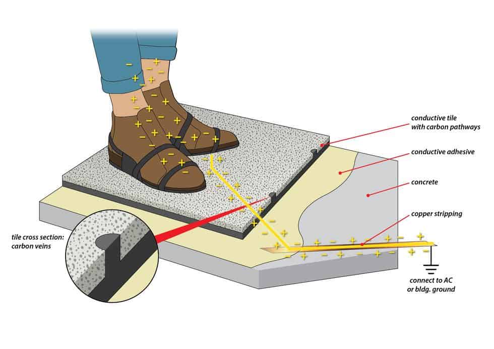
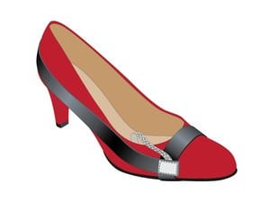
ESD footwear will drain static at the same rate as it is generated—as long as the footwear makes proper electrical contact with the conductive additives in the floor. In some cases, contact between the footwear and conductive fibers in the floor may be insufficient to properly drain static charges. If the ESD footwear has a small surface area, for instance, it may not make proper electrical contact with the floor. Most people lift one foot as they walk. Given the tiny conductive surface on a heel or toe strap, the foot on the ground could easily overstep the conductive fibers in the floor, preventing static from discharging to ground.
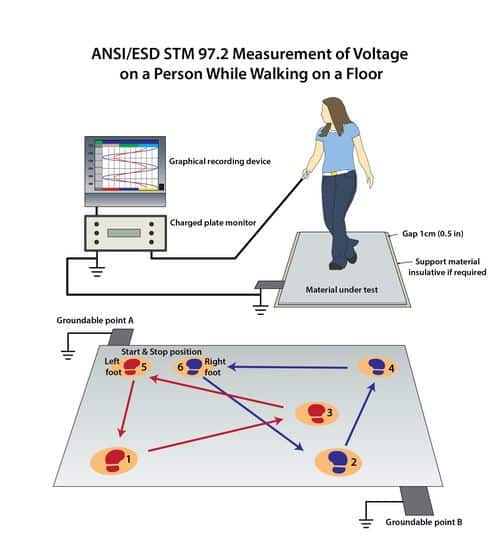
Due to tribocharging, static-dissipative vinyl and certain ESD epoxy coatings perform poorly even when used with some ESD footwear. The only way to know if a floor will prevent static from accumulating is, first, to determine what types of footwear will be worn in the environment. Second, to test a sample installation prior to installing the floor, per STM97.2, with the test subject wearing each type of footwear to be worn in the space (ESD and non-ESD, if applicable).
Most electronics facilities have protocols in place requiring all personnel to wear ESD footwear. If protocols are not in place—or not enforced—specifiers should select a floor that will prevent and inhibit static regardless of the type of footwear people choose to wear in the environment.
Not all footwear is created alike.
Static generation depends, not only on the flooring material, but the shoes people wear in the space. Leather is a naturally low-charge generating material due to its unique triboelectric properties and tendency to absorb moisture, such as ground water or sweat*; for this reason, shoes with leather soles tend to generate less static than most other types of street shoes.** Hiking shoes with electrically insulative polyurethane soles, on the other hand, generate greater static charges than other street shoes.
* At lower humidity ranges, leather is not always anti-static, so when evaluating ESD flooring, it’s important to consider environmental factors, along with footwear and flooring material.
** Leather shoes generate too much static to meet the body voltage limits for ANSI-certified electronics manufacturing and handling.
ESD footwear will drain static at the same rate as it is generated—as long as the footwear makes proper electrical contact with the conductive additives in the floor. In some cases, contact between the footwear and conductive fibers in the floor may be insufficient to properly drain static charges. If the ESD footwear has a small surface area, for instance, it may not make proper electrical contact with the floor. Most people lift one foot as they walk. Given the tiny conductive surface on a heel or toe strap, the foot on the ground could easily overstep the conductive fibers in the floor, preventing static from discharging to ground.
Due to tribocharging, static-dissipative vinyl and certain ESD epoxy coatings perform poorly even when used with some ESD footwear. The only way to know if a floor will prevent static from accumulating is, first, to determine what types of footwear will be worn in the environment. Second, to test a sample installation prior to installing the floor, per STM97.2, with the test subject wearing each type of footwear to be worn in the space (ESD and non-ESD, if applicable).
Most electronics facilities have protocols in place requiring all personnel to wear ESD footwear. If protocols are not in place—or not enforced—specifiers should select a floor that will prevent and inhibit static regardless of the type of footwear people choose to wear in the environment.
Not all footwear is created alike.
Static generation depends, not only on the flooring material, but the shoes people wear in the space. Leather is a naturally low-charge generating material due to its unique triboelectric properties and tendency to absorb moisture, such as ground water or sweat*; for this reason, shoes with leather soles tend to generate less static than most other types of street shoes.** Hiking shoes with electrically insulative polyurethane soles, on the other hand, generate greater static charges than other street shoes.
* At lower humidity ranges, leather is not always anti-static, so when evaluating ESD flooring, it’s important to consider environmental factors, along with footwear and flooring material.
** Leather shoes generate too much static to meet the body voltage limits for ANSI-certified electronics manufacturing and handling.


 Technically, flooring does not meet S20.20. That’s because ANSI/ESD S20.20 is not a specification. It’s a process document. A floor meets (or doesn’t meet) the recommended electrical parameters derived from the standard test methods referenced in S20.20.
In fact, S20.20 references not one, but three standard test methods, listed below.
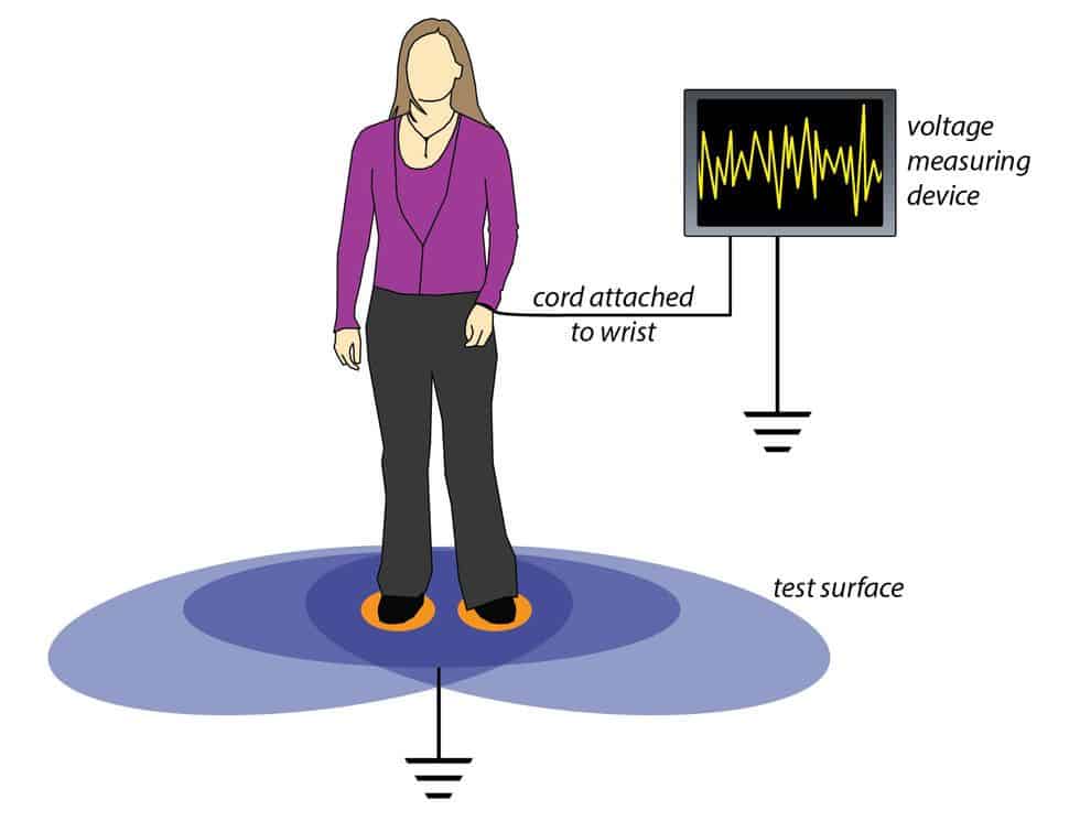
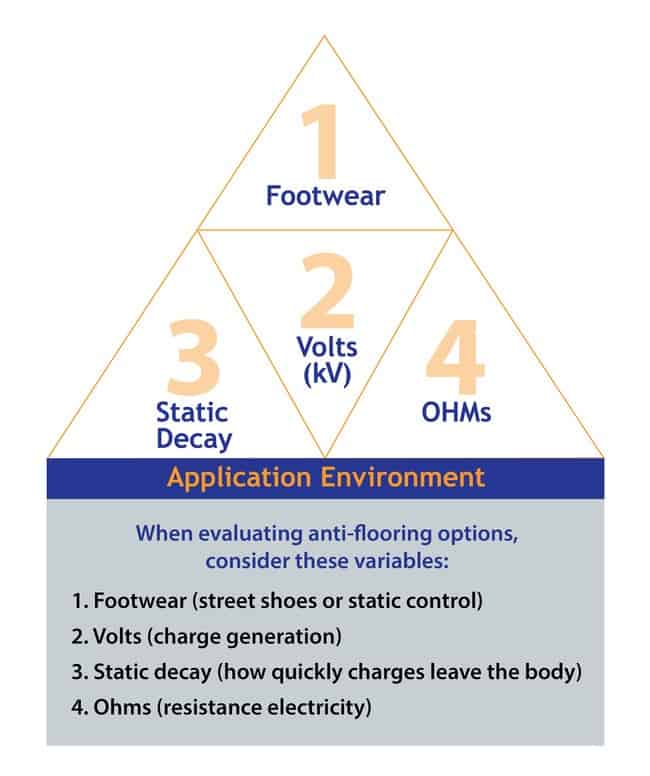
The first two methods test resistance properties, measured in ohms. The third, measured in volts, tests walking body voltage, or charge generation—crucial in determining the functionality of an ESD floor.

Independent lab testing of fiber-loaded, self-leveling epoxy floors proved that a floor can generate 100s of volts of static on a person wearing ESD heel straps—even when the floor measures in the conductive range. At 100 volts+, static could destroy components the floor is meant to protect. That’s the reason ANSI/ESD S20.20 requires all three tests.
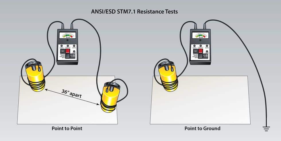
ANSI/ESD STM7.1
Floor Materials—Resistive Characterization of Materials. This standard says that flooring material must measure below 1.0 x 10E9 ohms to ground. The flooring material must also comply with the 2 parameters listed below:
ANSI/ESD STM97.1
Floor Materials and Footwear—Resistance in Combination with a Person. The recommended maximum system resistance is 1 x 10E9 ohms.
Technically, flooring does not meet S20.20. That’s because ANSI/ESD S20.20 is not a specification. It’s a process document. A floor meets (or doesn’t meet) the recommended electrical parameters derived from the standard test methods referenced in S20.20.
In fact, S20.20 references not one, but three standard test methods, listed below.
The first two methods test resistance properties, measured in ohms. The third, measured in volts, tests walking body voltage, or charge generation—crucial in determining the functionality of an ESD floor.
Independent lab testing of fiber-loaded, self-leveling epoxy floors proved that a floor can generate 100s of volts of static on a person wearing ESD heel straps—even when the floor measures in the conductive range. At 100 volts+, static could destroy components the floor is meant to protect. That’s the reason ANSI/ESD S20.20 requires all three tests.
ANSI/ESD STM7.1
Floor Materials—Resistive Characterization of Materials. This standard says that flooring material must measure below 1.0 x 10E9 ohms to ground. The flooring material must also comply with the 2 parameters listed below:
ANSI/ESD STM97.1
Floor Materials and Footwear—Resistance in Combination with a Person. The recommended maximum system resistance is 1 x 10E9 ohms.
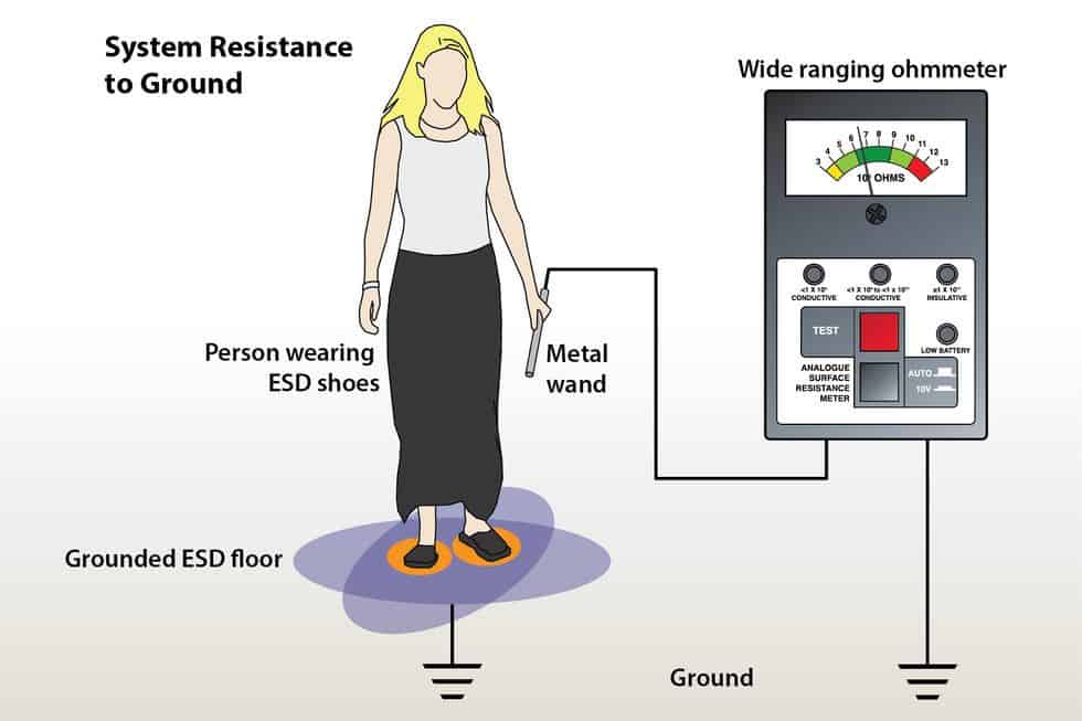
System resistance, measured through a person and footwear, yields a different value than testing the resistance of the flooring material alone, using 5-pound NFPA probes.
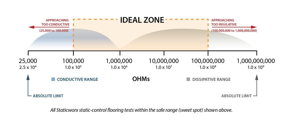
 When resistance to ground (Rtg) of a flooring material exceeds 1.0 x 10E8, the system (including the person, the footwear, and the floor) may not be able to compensate for the high resistive properties of the ESD footwear. The complete system may actually measure well over 1.0 x 10E9.
Let’s assume the flooring material measures 1 x 10E8, within the acceptable resistance range. For the system resistance test, the person, standing on that same floor, is wearing static-dissipative shoes. It would be difficult—if not impossible—for a flooring material measuring 1.0 x 10E8, combined with footwear that’s also in the upper end of the resistance range, to be part of a total system measuring less than 1 x 10E9. The math just doesn’t work.
Again, most static-dissipative coatings—and some conductive floors—cannot prevent body voltages from exceeding 100 volts. Since the goal of ANSI/ESD S20.20 is to prevent body voltages above 100 volts, it is impossible to categorically state that all static-dissipative and conductive floors measuring less than 1.0 x 10E9 meet ANSI/ESD S20.20. In fact, it is highly unlikely.