


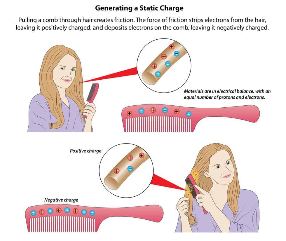
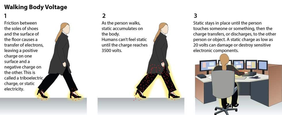
Static electricity results from the frictional contact between two chemically dissimilar materials. Dragging a comb through your hair, rubbing a balloon against a nylon shirt, and walking across a floor all generate static charges. The voltage remains on the surface of your body—static—until you touch another person or an object with some electrical conductivity (a metal doorknob, for example), then the charge jumps to that person or object.
 Like all electrical current, static electricity seeks its easiest path to ground. We call this the “path of least resistance.” The person or object you touch provides a potential pathway to ground. This sudden transfer of electrical current (or static electricity) is called an electrostatic discharge, or ESD.
To notice the effects of static electricity, the discharge must be at least 3500 volts—the threshold for human perception. But a discharge as tiny as 500 volts—or, in the case of highly sensitive microcircuits, 100, or even 20 volts—can jumble data and damage or destroy the ultra-sensitive, high-speed microcircuits inside high performance electronic components.
Static electricity results from the frictional contact between two chemically dissimilar materials. Dragging a comb through your hair, rubbing a balloon against a nylon shirt, and walking across a floor all generate static charges. The voltage remains on the surface of your body—static—until you touch another person or an object with some electrical conductivity (a metal doorknob, for example), then the charge jumps to that person or object.
Like all electrical current, static electricity seeks its easiest path to ground. We call this the “path of least resistance.” The person or object you touch provides a potential pathway to ground. This sudden transfer of electrical current (or static electricity) is called an electrostatic discharge, or ESD.
To notice the effects of static electricity, the discharge must be at least 3500 volts—the threshold for human perception. But a discharge as tiny as 500 volts—or, in the case of highly sensitive microcircuits, 100, or even 20 volts—can jumble data and damage or destroy the ultra-sensitive, high-speed microcircuits inside high performance electronic components.
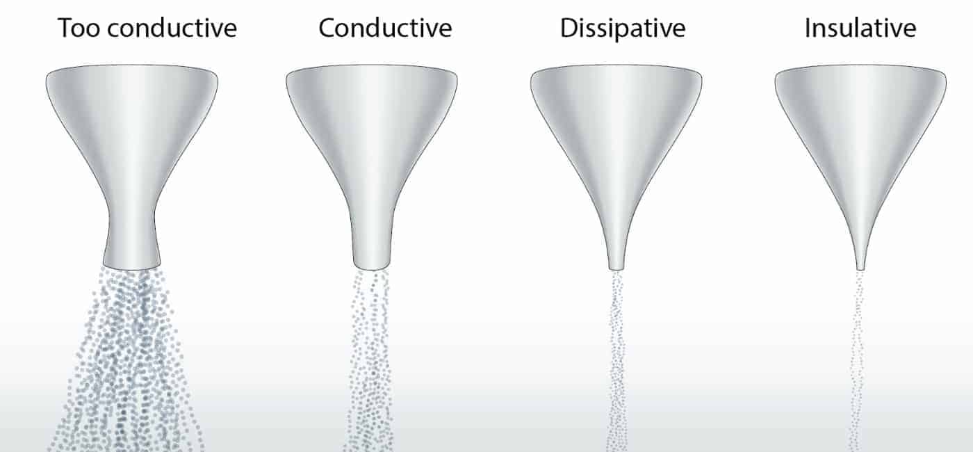
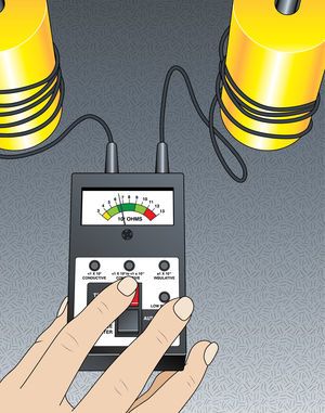
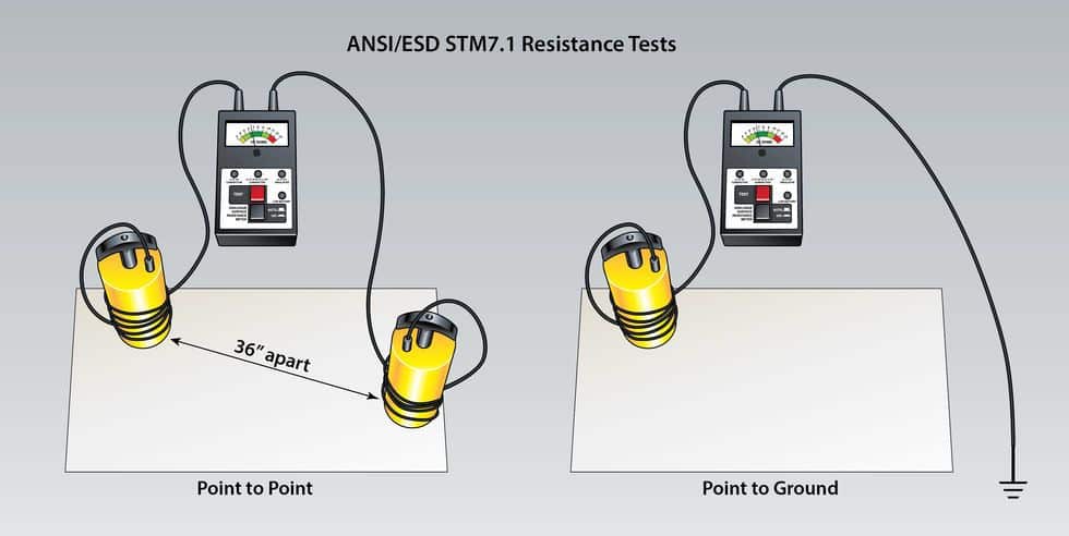
To predict how efficiently (how quickly or slowly) an ESD floor will ground static charges, we measure the electrical resistance of the flooring material using an ohm meter.
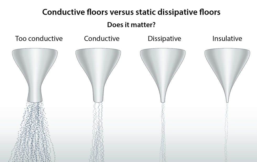
 Resistance is the opposite of conductivity—the capacity of a material to slow, or resist, the flow of electricity. If resistance is low—the floor is more conductive—charges will flow quickly. If resistance is high—the floor is dissipative (or less conductive)—charges will have a harder time moving and flow more slowly.
Resistance standards in every industry follow the procedures outlined in ESD Standard Test Method 7.1. Using an instrument called an ohm meter, we measure the electrical resistance of the flooring material in ohms (Ω).
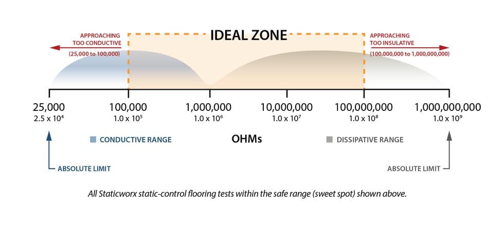
- Flooring materials measuring less than or equal to 1.0 x 10E6 are considered conductive.
- Flooring materials measuring greater than 1.0 x 10E6 and less than or equal to 1.0 x 10E9 are considered static-dissipative.
To predict how efficiently (how quickly or slowly) an ESD floor will ground static charges, we measure the electrical resistance of the flooring material using an ohm meter.
Resistance is the opposite of conductivity—the capacity of a material to slow, or resist, the flow of electricity. If resistance is low—the floor is more conductive—charges will flow quickly. If resistance is high—the floor is dissipative (or less conductive)—charges will have a harder time moving and flow more slowly.
Resistance standards in every industry follow the procedures outlined in ESD Standard Test Method 7.1. Using an instrument called an ohm meter, we measure the electrical resistance of the flooring material in ohms (Ω).
- Flooring materials measuring less than or equal to 1.0 x 10E6 are considered conductive.
- Flooring materials measuring greater than 1.0 x 10E6 and less than or equal to 1.0 x 10E9 are considered static-dissipative.

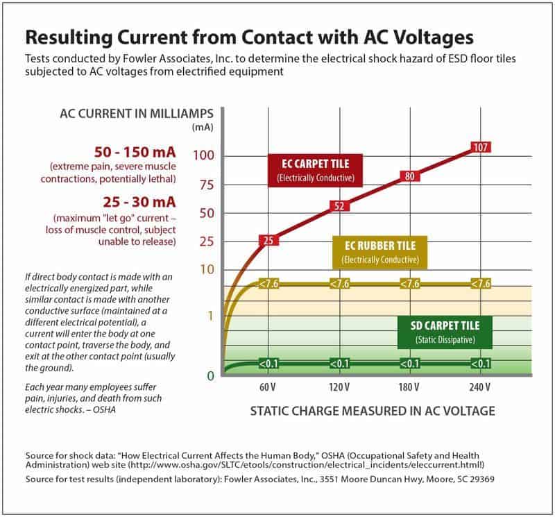
As a safety consideration for end-user environments housing electrified equipment, footwear should be factored into the equation. Because a built-in resistor limits exposure to electrical current, static-control footwear provides protection against electrical shock that regular footwear simply doesn’t offer. If static-control footwear can’t be used or its usage can’t be enforced, the floor needs to compensate for this condition.

Footwear also affects the electrical performance of some ESD flooring materials. Vinyl, for instance—whether conductive or dissipative—can be a static-generating material. When people in regular (street) shoes walk on a conductive vinyl floor, the contact between the floor and soles of their shoes can generate significant static charges.
In conjunction with ESD footwear, vinyl performs well. That’s because the conductive elements in static-protective footwear form an electrical bond with the embedded carbon in ESD vinyl, preventing static charges from building on the person or soles of his or her shoes.
While conductive or dissipative vinyl floor can perform well, in electronics applications with footwear mandates, it cannot address the static-control challenges of an end-user environment. Without static-protective footwear, ESD vinyl performs no better than a regular (not-ESD) static-generating floor.
In the case of conductive carpet (a multi-layer composite construction), a conductive backing electrically connects the surface of the tiles—through the conductive fibers in the yarn bundles, via conductive precoat to the conductive fiberglass and carbon-loaded black backing, to the conductive adhesive or underlayment, to ground. Most conductive carpet tile installations measure above 25,000 ohms, typically 2.5 x 10E4 to 1.0 x 10E5. But any increase in moisture in the environment—a rise in ambient RH or changes in the concrete dew point—would increase the conductivity of the tiles, and could reduce the floor’s electrical resistance below the level of acceptibility.
In an electronics application, where mandates require the use of ESD footwear, low conductivity is typically not a problem. In an end-user space, with people wearing regular street shoes and working with energized equipment, it could pose a safety risk.
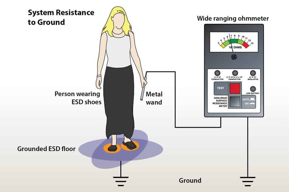
Installing highly conductive carpet over a less conductive adhesive will raise system resistance—that is, the resistance of the entire system; carpet, adhesive, and shoes worn by the test subject, standing on the carpet—masking the problem. The resistance of the carpet itself doesn’t go up.

Remember: systems readings, the resistance of the carpet simply seems higher. Potential safety risks are the same.
The PVC backing on static-dissipative carpet, on the other hand, slows the flow of current from the walking surface, through the carbon fibers in the yarn to the conductive adhesive or subfloor. With a resistance of 10E6, dissipative carpet safely and effectively transports charges to ground—with no appreciable vulnerability from environmentally-induced fluctuations.
In the case of conductive carpet (a multi-layer composite construction), a conductive backing electrically connects the surface of the tiles—through the conductive fibers in the yarn bundles, via conductive precoat to the conductive fiberglass and carbon-loaded black backing, to the conductive adhesive or underlayment, to ground. Most conductive carpet tile installations measure above 25,000 ohms, typically 2.5 x 10E4 to 1.0 x 10E5. But any increase in moisture in the environment—a rise in ambient RH or changes in the concrete dew point—would increase the conductivity of the tiles, and could reduce the floor’s electrical resistance below the level of acceptibility.
In an electronics application, where mandates require the use of ESD footwear, low conductivity is typically not a problem. In an end-user space, with people wearing regular street shoes and working with energized equipment, it could pose a safety risk.
Installing highly conductive carpet over a less conductive adhesive will raise system resistance—that is, the resistance of the entire system; carpet, adhesive, and shoes worn by the test subject, standing on the carpet—masking the problem. The resistance of the carpet itself doesn’t go up.
Remember: systems readings, the resistance of the carpet simply seems higher. Potential safety risks are the same.
The PVC backing on static-dissipative carpet, on the other hand, slows the flow of current from the walking surface, through the carbon fibers in the yarn to the conductive adhesive or subfloor. With a resistance of 10E6, dissipative carpet safely and effectively transports charges to ground—with no appreciable vulnerability from environmentally-induced fluctuations.
Inconsistency in readings for material and system resistance suggest that resistance values have been artificially altered by a component in the flooring system and should be investigated.
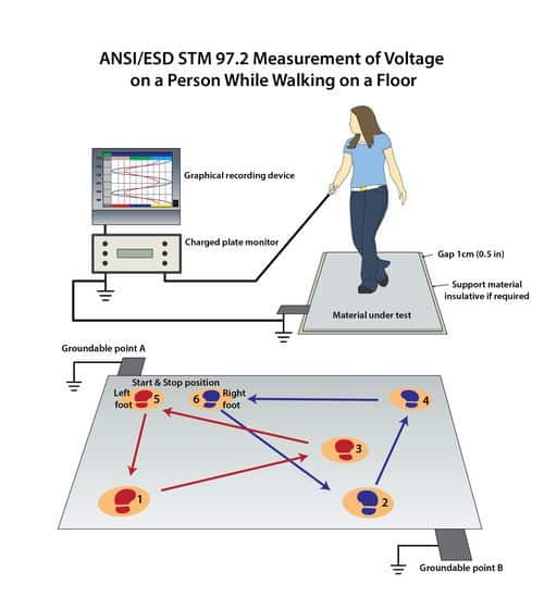
To determine whether the floor will generate static when people walk, follow ANSI/ESD STM97.2 to test walking body voltage.
System resistance and body voltage tests should always be performed with the test subject wearing footwear that’s as close as possible to the shoes people are likely to wear in the space.
To Avoid Confusions, Eliminate the Terms Conductive & Dissipative from Conversations About ESD Floors.
While conductive and dissipative may be useful for interpreting electrical standards, specifying a floor based only on resistance values is asking for trouble. Rather than deal with needless confusion—or risk specifying a floor that ultimately fails—it’s wise to eliminate the terms conductive and dissipative from conversations on the specification or selection of an ESD floor.
To be sure the floor you select will provide adequate static protection and prevent damage from random static discharge:
- Take the time to learn and understand industry-applicable standards like FAA 019f, ATIS 0600321-2015, Motorola R56, and ANSI/ESD S20.20;
- Take stock of the environment and application, paying particular attention to the shoes people will wear in the space;
- Be aware that some ESD floors can generate significant static charges on people wearing regular street shoes;
- Evaluate materials based on chemical and physical makeup;
- And always test the floor, following the procedures outline in STM97.2, to evaluate charge generation, and STM7.1, to be sure it meets the promised resistance criteria.