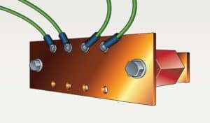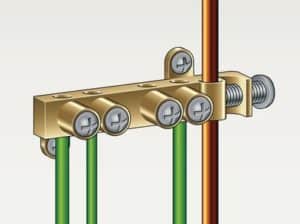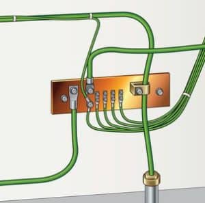

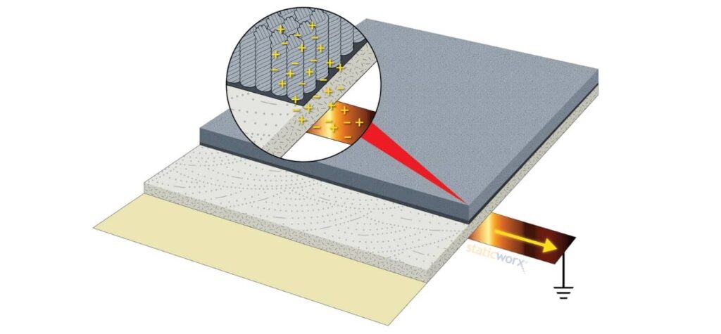
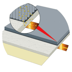

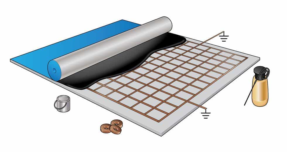
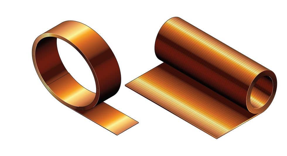
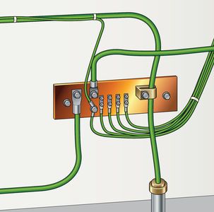
 The conductive adhesive is linked to ground with copper connector straps placed at the perimeters of the room. The straps, usually about 24” long, can be attached to electrical outlets, conduit, building steel, or a dedicated grounding bar. Only one connection is necessary for every 1000 square feet of contiguous ESD flooring.
The conductive adhesive is linked to ground with copper connector straps placed at the perimeters of the room. The straps, usually about 24” long, can be attached to electrical outlets, conduit, building steel, or a dedicated grounding bar. Only one connection is necessary for every 1000 square feet of contiguous ESD flooring.
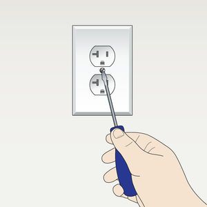
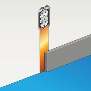
Step 5
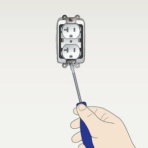
 Allow 24″ copper strap to run down wall to subfloor (concrete, etc.).
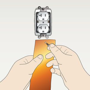
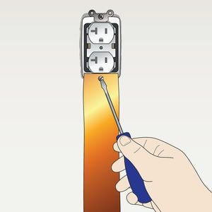
Fold copper at a 90-degree angle at the point where the wall meets the floor. Lay remainder of copper strap flat on the subfloor. The strap can be placed directly on the concrete subfloor in advance of installation or pressed into the conductive adhesive during installation.
At least 6 inches of copper should contact the floor. If the copper is applied directly to bare concrete or another subfloor, it will need to be covered with conductive adhesive during the installation.
Allow 24″ copper strap to run down wall to subfloor (concrete, etc.).
Fold copper at a 90-degree angle at the point where the wall meets the floor. Lay remainder of copper strap flat on the subfloor. The strap can be placed directly on the concrete subfloor in advance of installation or pressed into the conductive adhesive during installation.
At least 6 inches of copper should contact the floor. If the copper is applied directly to bare concrete or another subfloor, it will need to be covered with conductive adhesive during the installation.
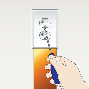
 Any electrical outlet can be tested using a ground plug tester.
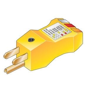
A Ground Plug Adapter is equipped with three indicating lights. The ONLY indication that is acceptable for the Ground Plug Adapter to be in use is with the two outer “CIRCUIT OK” lights energized, i.e., Lights #1 and #3 ON, Light #2 OFF.

Step 1
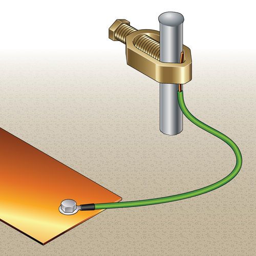 Drive the 4- to 6-foot rod into the ground until only 2 or 3 inches of the rod remains exposed.
Step 2
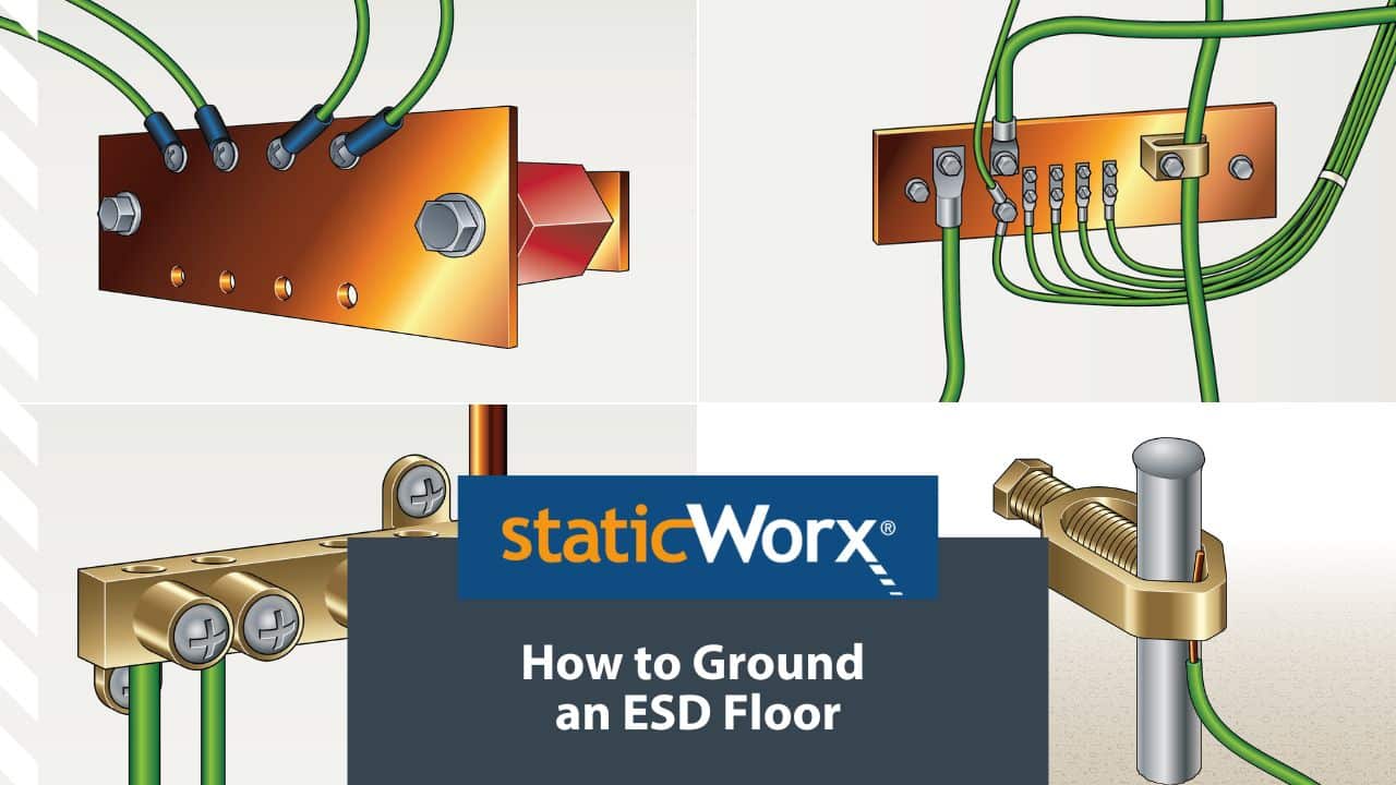
Attach the copper-grounding strap to the exposed end of the rod using a grounding clamp, usually sourced from the same manufacturer as the grounding rod (refer to www.stormgrounding.com.) If necessary, a #10 or #12 wire can be attached to the grounding rod.
Step 3
Run the wire from the rod to the grounding strap, and tie it to the strap with a wire nut.
Step 1
Drive the 4- to 6-foot rod into the ground until only 2 or 3 inches of the rod remains exposed.
Step 2
Attach the copper-grounding strap to the exposed end of the rod using a grounding clamp, usually sourced from the same manufacturer as the grounding rod (refer to www.stormgrounding.com.) If necessary, a #10 or #12 wire can be attached to the grounding rod.
Step 3
Run the wire from the rod to the grounding strap, and tie it to the strap with a wire nut.
Step 1
 Affix the grounding strap to the tile as described in paragraph one.
Step 2
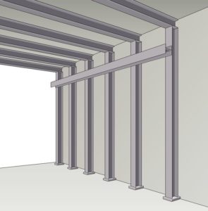
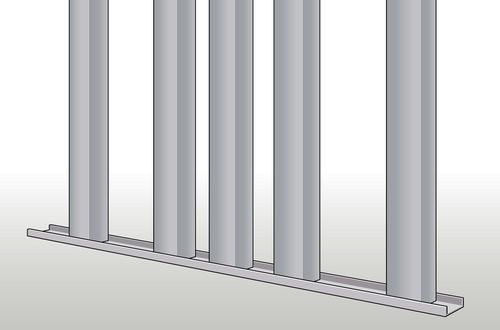
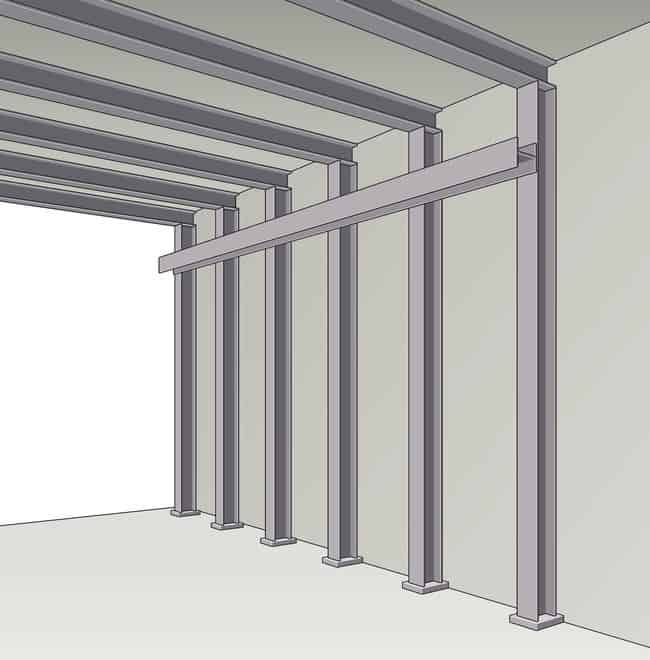
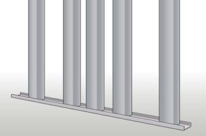
Drill a hole in the support column.
Step 3
With a grounding screw or clamp, attach the end of the copper strap directly to the column. Or mount a grounding clamp to the column and use it to clamp the copper strap.
Copper grounding straps should be attached to aluminum studs using sheet metal screws and a washer.


Step 1
Affix the grounding strap to the tile as described in paragraph one.
Step 2
Drill a hole in the support column.
Step 3
With a grounding screw or clamp, attach the end of the copper strap directly to the column. Or mount a grounding clamp to the column and use it to clamp the copper strap.
Copper grounding straps should be attached to aluminum studs using sheet metal screws and a washer.