

Resistance, Resistivity, and Real World Application
[11 min read, 6 min videos]
If you don’t have an electrical engineering degree or real-world equivalent, the terms resistance and resistivity can be confusing. The terms are particularly confusing because people tend to use them interchangeably—and resistance and resistivity are not interchangeable.

Resistance
Resistance is the capacity of a material to resist, or stop, the flow of electrical currents.
Resistance readings are measured in ohms (Ω). The optimal resistance for ESD flooring materials is between 1 x 10E5 (100,000 or 1 hundred thousand) and 1 x 10E8 (100,000,000 or 1 hundred million) ohms.
As Ohm’s law tells us, resistance is equal to the ratio of voltage to current. Here’s the equation:
E=IR (for d.c. potentials)
R= V/I
R = resistance, V= voltage, I = current/amps
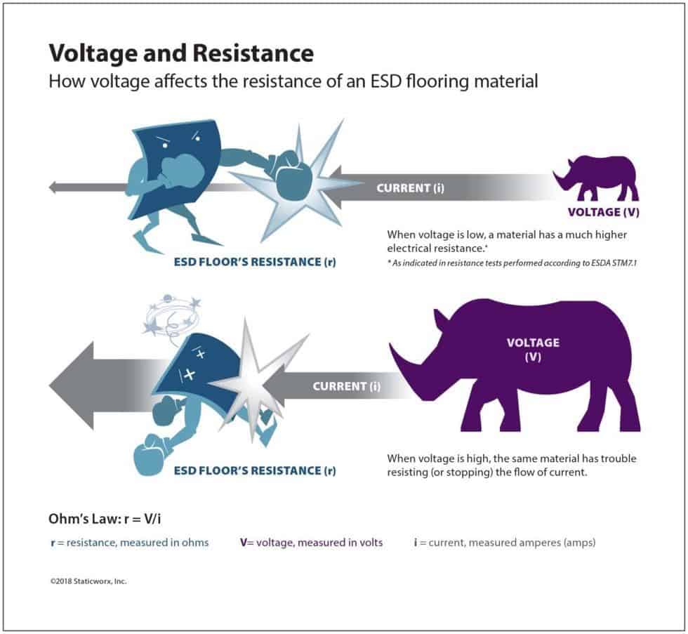
As you can see from the equation, current varies depending upon the applied voltage. Resistance readings are also affected by other factors, including temperature, humidity, the cleanliness of the test material, as well as size and shape of the probes used in the testing.
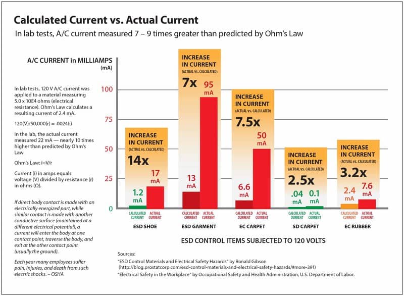
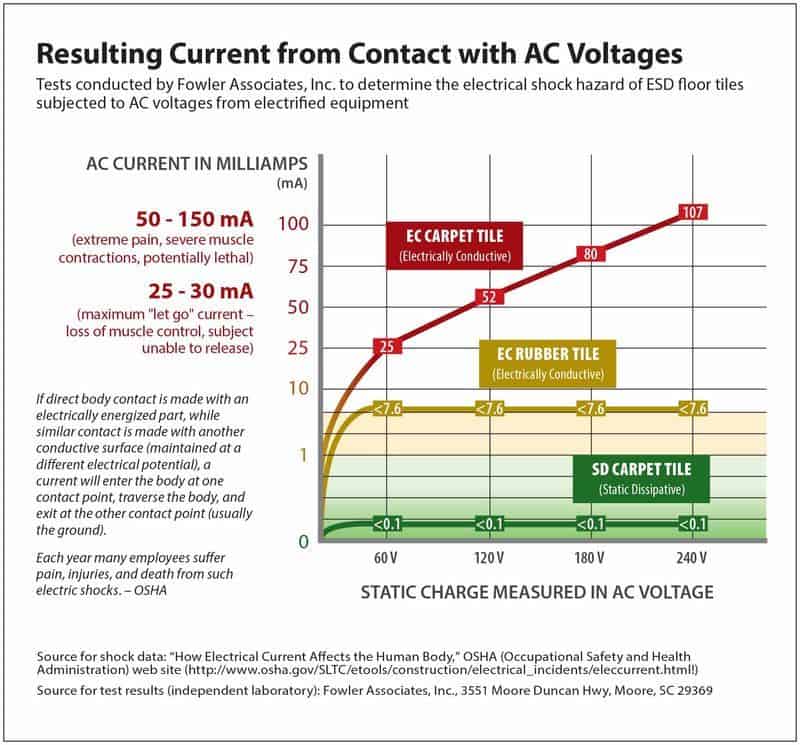
In laboratory testing, actual currents produced by applying AC voltage to an ESD flooring material were even higher than calculations based on Ohm’s law.
Resistivity
Resistivity, measured in ohms per square, is an inherent property of a homogeneous material.* Tests are done in a controlled manner that produces repeatable data. Absolute resistivity does not change, nor is it affected by temperature, humidity, or other external factors. However, as these external factors can affect the ability to measure resistivity, readings may vary.
- While resistivity can predict the resistance of a homogeneous material, it cannot predict the resistance of a laminate or non-homogeneous material.
In the ESD flooring industry, we don’t concern ourselves with resistivity. We’re more interested in knowing how a material will perform under real-world circumstances.
Resistance Testing
We use resistance tests to measure the resistance of ESD flooring materials. ANSI/ESD S20.20-2021 requires two resistance tests:
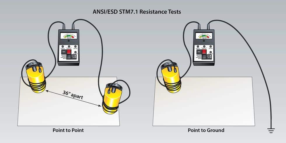
ANSI/ESD STM7.1-2013 Tests the resistive characterization of flooring materials.
In STM 7.1, two conductive probes are placed on a material or tile, 36” apart, then an ohmmeter applies 10 volts of d.c. current and the ohmmeter displays a reading, showing how much electrical resistance the current met as it crossed the material.
ANSI/ESD STM97.1 Measures the electrical system resistance of floor materials in combination with persons wearing static-control footwear.
In STM97.1 the test subject (person) stands on an installed floor. Completely different from 7.1, STM97.1 measures total system resistance—i.e., the resistance of the person, wearing shoes they’ll wear in the environment, the flooring material, and the adhesive.
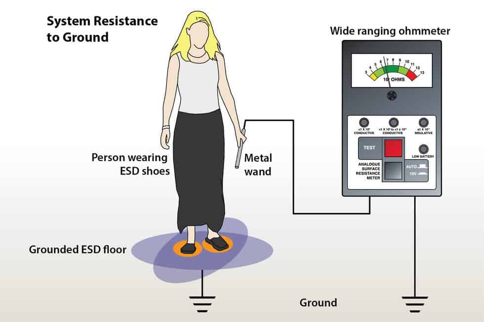
To accurately predict system resistance—and charge generation in walking body voltage tests—the subject should wear the shoes that will actually be worn in the environment.
If ESD footwear is required, the person should wear the exact shoes or footwear (e.g., heel straps) ordered for use in the space. If people will wear regular footwear on the floor, the test should be done with the subject in various types of regular street shoes.
Is it important to perform both tests?
Absolutely! S7.1, typically done during the qualification or selection process, predicts how the floor will respond to electrical currents, and whether it will safely and effectively conduct charges to ground. As 97.1 includes actual real-world variables, results show how the material will perform in the environment. It also assures the buyer that the floor they specified is the floor they bought and installed. In other words, the promised and predicted resistance is the resistance they got.
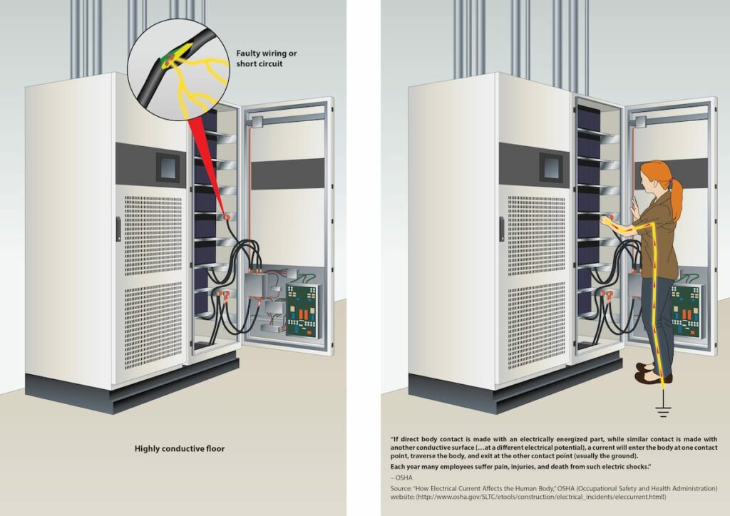
In most cases, resistance values are a cumulative measurement of a conductive surface and a more conductive adhesive or underlayment. If the surface of the flooring material is highly conductive, or more conductive than the conductive underlayment or adhesive, the surface of the floor could form a ground circuit with a piece of nearby energized equipment, with much less resistance than intended. Standards like FAA 019f require resistance to measure above 1.0 x 10E6 for this very reason.

✓ visual selector guide;
✓ walking body voltage/low static generation;
✓ resistance requirements and testing;
✓ ESD flooring comparison;
✓ industry standards & test methods;
✓ key ESD terms
Resistance Tests and Applied Voltage
As noted above, applied voltage influences the results of resistance testing. Low resistance specifications are often based on an outdated standard, NFPA 99, designed by the National Fire Protection Association in the 1950s to protect against the explosion of flammable materials in hospital environments. For safety reasons, the NFPA set minimum resistance at no lower than 2.5 x 10E4.
NFPA 99 was done with two five-pound probes, following a method very similar to ESD 7.1. The difference—and it’s huge—is that NFPA 99 tested material resistance using 500 volts of applied current. Five hundred volts of applied current is a pretty big zap. Big enough for the resistance of a moderately conductive material to appear to be quite low. ANSI/ESD S7.1, on the other hand, tests with 10 or 100 volts (depending upon initial readings*). This far lower voltage generally yields much higher resistance readings.
- If the initial reading at 10 V is under 1.0 x 10E6, that reading is recorded. If the reading is above 1.0 x 10E6, the material is re-tested with 100 V of applied current.
As we know from Ohm’s law, the higher the applied voltage, the higher the current for a fixed resistance. Tested at 500 volts of applied potential, a material measuring 2.5 x 10E4 per STM7.1 (an already low reading) could yield a dangerously low resistance.*
- If the applied voltage is high enough, the material being tested could be damaged by an electrical arc, in which case the resistance will actually be lowered.
Why Does Low Resistance Matter?
As the NFPA—and OSHA—acknowledge, excessively low resistance is a safety hazard.
As we’ve shown above, how resistance tests are done affects the results. When low readings are cited as an acceptable minimum resistance, we need to ask where the numbers came from. If someone claims a material is safe because it passes NFPA 99, with resistance readings of 2.5 x 10E4, either they tested the material in question with 500 volts of applied current or they’re pulling a fast one.
Furthermore, NFPA 99 no longer covers ESD flooring, so the standard doesn’t even apply.
Current standards set by the telecom industry and Federal Aviation Administration—Motorola R56 and FAA 019f—prohibit flooring materials measuring under 1 x 10E6 in areas where energized equipment is in use. Both OSHA and the data center industry use the same number.
Optimal Resistance
Resistance can be too low. It can also be too high. A flooring material with a resistance measuring 1.0 x 10E9 ohms, the upper limit permitted under ANSI/ESD S20.20-2021, may have too much electrical resistance to safely discharge static to ground. As noted above, resistance is affected by numerous factors—including temperature, humidity, and cleanliness. Even if a flooring material reading 10E9 performs well when it’s installed, low temperatures, dry air, and dirt can all raise electrical resistance to the point that the floor falls out of the acceptable range.

The Sweet Spot
To avoid resistances that are too low, posing a possible safety risk, or too high, potentially preventing the floor from adequately protecting equipment from the damaging effects of random ESD events, StaticWorx recommends a resistance range within what we call “the Sweet Spot.”
That is, between 1 x 10E5 and 1 x 10E8 ohms.
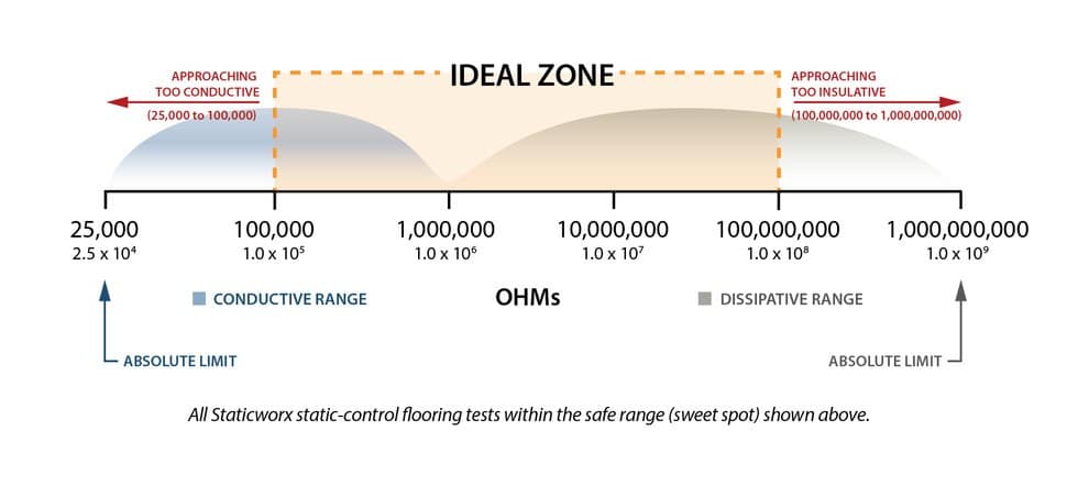
Materials at the low end of the range are perfectly acceptable—and safe—in electronics manufacturing and handling environments (EMA) where everyone in the space is required to use ESD footwear, and EPA mandates are enforced. In these spaces, low-resistive floors are safe because the built-in resistors in ESD footwear also protect the wearer from electrical shock.
At the high end, 1 x 10E8, the floor has ten times—an entire magnitude—less resistance than materials measuring 10E9. This gives the material plenty of wiggle room to stay within range.
Get in Touch
The form below will help us better understand your needs and get you as quickly as possible to the right person. We look forward to helping you solve your static problem!
You can expect a response within 24 hours. For faster service, please give us a call: 617-923-2000
"*" indicates required fields
Visit our privacy policy to find out how we process data.


Learning Center Articles
- ESD Basics
- Installation & Maintenance
- Selecting & Specifying an ESD Floor
- Technical Information
- 7 Common Mistakes Selecting an ESD floor
- A Guide to ESD Flooring Selection
- Avoid Costly Failures: What You Need to Know When Specifying ESD Flooring
- Choosing ESD Flooring for:
- ESD Footwear: What Is It and When Is It Necessary?
- ESD Footwear for Electronics Manufacturing and Handling Applications
- Facility Managers’ Guide to Selecting ESD Flooring
- The Need for Due Diligence in Specifying Static-Free Flooring
- Standard of Care for Specifying Floors in Mission-Critical Spaces
- Understanding the Hidden Costs of ESD Flooring

StaticWorx high-performance static-control floors protect electronic components, explosives, and high-speed computers from damage caused by static electricity. ESD flooring is part of a system. Choices should always be based on objective, researched evidence. When you partner with us, we look at all possible items that may need to integrate with the floor, and, focusing on your goals and objectives, help you find the right floor for your application.