

Learn the differences between ESD solid vinyl tile and interlocking ESD tile. The post compares specs, installation, maintenance and intangibles.

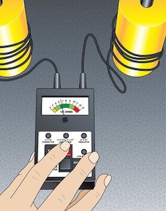 You finally received your new portable ohm meter with the five-pound probe and someone showed you how to use it. Just drop the two five-pound probes on the floor, connect leads to the meter and hit the test button. That’s all you need to do. Right?
Not even close.
Let’s start with your mission. What are you doing and why are you doing it?
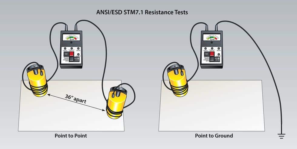
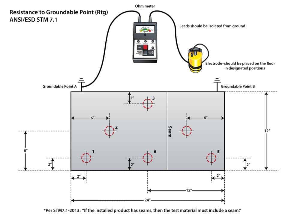
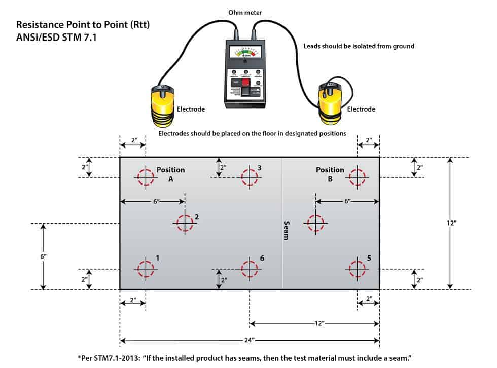
Hopefully your goal is to identify flooring options that meet standards like ANSI/ESD S20.20. To meet standards, you need to utilize standard test methods. When it comes to ESD flooring, the test method you need to follow is ANSI/ESD STM 7.1-2013. Do you have a copy of this test method? If you don’t have a copy, you can order it here on ESDA.org.


To maintain performance, ESD floors require specially formulated products. We offer tips on what to consider when choosing cleaning supplies.

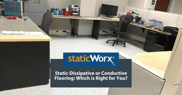
Static-dissipative floors transport harmful static charges to ground. Dissipative is also a term for flooring with a specific, measurable electrical resistance.

StaticWorx recognized as one of the fastest growing private companies in the U.S. 2023 marks StaticWorx fourth appearance on Inc. 5000 list.

Conductive and dissipative flooring protect electronics by transporting charges to ground, conductive at a quicker rate, dissipative slower & more controlled.
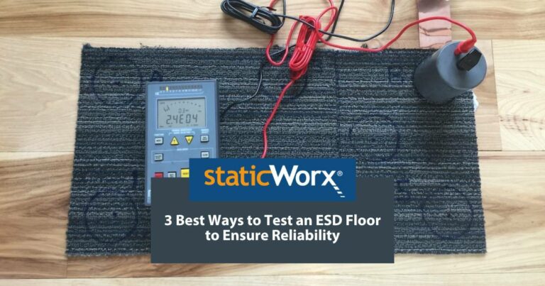
We explain the 3 main ways to test an ESD floor: Electrical resistance; body voltage & ESD audits, with advantages and reasons for each.
Three critical factors—application, industry standards & footwear—help you choose the best ESD floor, while ensuring the safety & efficiency of your operations.

StaticWorx Founder and President Dave Long shares three of his recommended reads: Quit, How to Change, and The Goal.

There are leadership qualities StaticWorx strives to embody every day, with every product, throughout each project.

No matter how you slice and dice a project, an ESD floor is a major investment. This blog post examines five ways to keep undue costs down.

What’s the difference between static control and static resistant? Or anti-static flooring? Find out more in our blog post.

A major part of any ESD control program is getting proper flooring in place. How can one replace a floor without generating any debris? Learn more.

A well-designed, comprehensive, fully realized program is a must for manufacturers serious about ESD control. Learn why ESD programs fail.

ESD Floors should never be specified based on the descriptive terms conductive or static dissipative. Always base ESD specs on verifiable metrics. Find out why.

<a class="eael-grid-post-link" href="https://staticworx.com/case-studies/esd-flooring-failure-incorrect-testing/" title="Blog Post: Case Study: ESD Flooring Failure, Incorrect Testing: Always Qualify Your Floor Using ANSI/ESD Test Methods">Blog Post: Case Study: ESD Flooring Failure, Incorrect Testing: Always Qualify Your Floor Using ANSI/ESD Test Methods
To comply with relevant ESD standards, test electrical properties using methods outlined in ESD S20.20. For best results require testing by an independent lab.

<a class="eael-grid-post-link" href="https://staticworx.com/installing/esd-flooring-installation-bond-test-manufacturer-oversight-critical/" title="Blog Post: ESD Flooring Installation:
Bond Test and Manufacturer Oversight Are Critical to ESD Flooring Success">Blog Post: ESD Flooring Installation:
Bond Test and Manufacturer Oversight Are Critical to ESD Flooring Success
If the vapor barrier fails to adhere to the subfloor, tiles will lift. Bond test and manufacturer oversight are crucial to ESD floor installation success.

<a class="eael-grid-post-link" href="https://staticworx.com/technical-info/conductive-static-dissipative-flooring-difference/" title="Blog Post: Conductive and Static-Dissipative Flooring: What’s the Difference?
The Layperson’s Answer">Blog Post: Conductive and Static-Dissipative Flooring: What’s the Difference?
The Layperson’s Answer
What’s the difference between conductive and static-dissipative flooring? Facts, analogies and images illustrate the difference in easily understood terms.

Qualifying an ESD floor helps ensure you get the floor you paid for. Find out why you should always qualify according to ESD S20.20
Will bare concrete control static? Learn why concrete floors are unreliable & what precautions to take if you must work on a bare concrete floor.

A look at how the StaticWorx cartoon, 'Conductive Flooring Does Not Mean Antistatic Flooring,' was conceived and created.